Editor’s note: A former engineer with Motorola, Mr. Allison is a frequent contributor to this newspaper. As electric vehicles, 5G Internet, and cyber-currencies proliferate, Allison explains how utilities must adapt in order to accommodate increasing demands upon The Grid.
USA – In Part 2 last week, you learned that AC current behaves differently from DC current. In this part, you will see how engineers are finding an “elegant solution” for moving extra electricity as the “Grid” will be called up to furnish ever-increasing quantities of AC power for the looming roll-outs of 5G wireless systems and electric vehicles.
As pointed out thus far in my series of articles on The Grid, there is a loss of about 15 percent of the power produced and fed into the Grid that does not provide any useful purpose. Ever wonder why birds line up on the power lines in the winter? As more power is delivered over the Grid’s wires, the temperature rises. As the temperature rises, less power passes through the wires, but at least the birds’ feet are warmed!
The Grid power lines often have steel cable in the middle of the wires for strength with copper wrapped around the steel to lower electrical resistance. The copper covering can be quite thin compared to the total width of the AC power wires. What happens when the wire has to carry more power than it is rated for? The solution most people would think of is to take the thin wire out and put in bigger diameter wires. Or, perhaps DOUBLE THE VOLTAGE, which cuts the current in half.
Let’s look at the system as a whole. If we install a larger wire, we have to know if the towers carrying the wire will take the weight and the wind load. In almost all cases, the weight of the wire is not a problem as the insulators will probably carry the quadrupled dead weight. The towers that support the wires will probably take the dead weight also. But the wires have wind resistance! Light winds in the summer would not be a problem either. However, in hurricanes and tornadoes, the wind load could easily be five to 15 times the dead weight. That could be a serious problem. Suppose in the winter we get ice sticking to the wires in a storm and there are significant winds. Now the power wires are heavier by the weight of the ice; the ice reshapes the wire’s round profile so the wires can “gallop” (swing back and forth) maybe even crashing into each other, and short out your power or knock down the supporting towers. That is messy!
Alternatively, suppose we double the voltage. This is an expensive option! Every power transformer on the lines where the voltage is doubled will have to be replaced. As transformers go higher in voltage, they become exponentially more costly. The wire windings in the transformer require thicker insulation. Also, because of the higher voltages, the plastic insulation between the layers of windings must also be thicker since at least the same volume of current as the original lower voltage must pass through to provide the double net power transmission increase that we are designing. The delivery time on new transformers of this quality could be as much as three years from order placement. Depending on the original line voltage, going to the higher voltage could also necessitate more insulators on the transmission lines. But wait! The extra length of more insulators could allow the wires to swing close to the tower and draw an arc, causing a loss of current-carrying capacity in the wire(s) that draw the arc.
Then what about the transformers needing to carry more current? Inserting some additional transformers to carry the higher current to nearby locations can save having to replace a large batch of them throughout the whole transmission line.
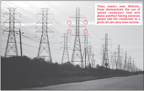
So what is the solution? If you drive to Raleigh on US 70, between Princeton and I-40 in the Smithfield area, if you look up at the high power lines you will see there are two or three power lines (conductors) running parallel to each other with non-conductive spacers at a fixed distance apart.
Why? You might say, “It’s a trick of the trade.” When AC power is flowing in parallel conductors, the magnetic field forces each conductor’s AC current deeper into the other wires. Let’s say Conductor A and B are spaced side by side. Conductor A’s magnetic field forces the current on Conductor B to penetrate deeper into its wire. At the same time, Conductor B’s magnetic field forces the current on Conductor A to penetrate deeper into its own wire. Likewise, Conductor C impacts Conductor A and Conductor B, and they also impact Conductor C. This lowers the resistance of each individual wire, thus allowing more power to be carried. If the spacers were not present, the wires could rub together, destroying the magnetic field, and limiting the total amount of current being carried.
Next time, the term “elegant solution” is explained. Also, we’ll receive a practical lesson on “Mean Time Between Failure” (MTBF), presented here for your fascination.
Related posts:

Gordon is a frequent contributor to The County Compass


